Back
Ball and Beam Experiment
This project implements a Ball and Beam control system to study the end-to-end development of a PID controller, from mathematical modeling and simulation to real-time embedded implementation. The objective was to analyze controller behavior, limitations of physical systems, and discrepancies between ideal models and real-world execution.
Repositry:

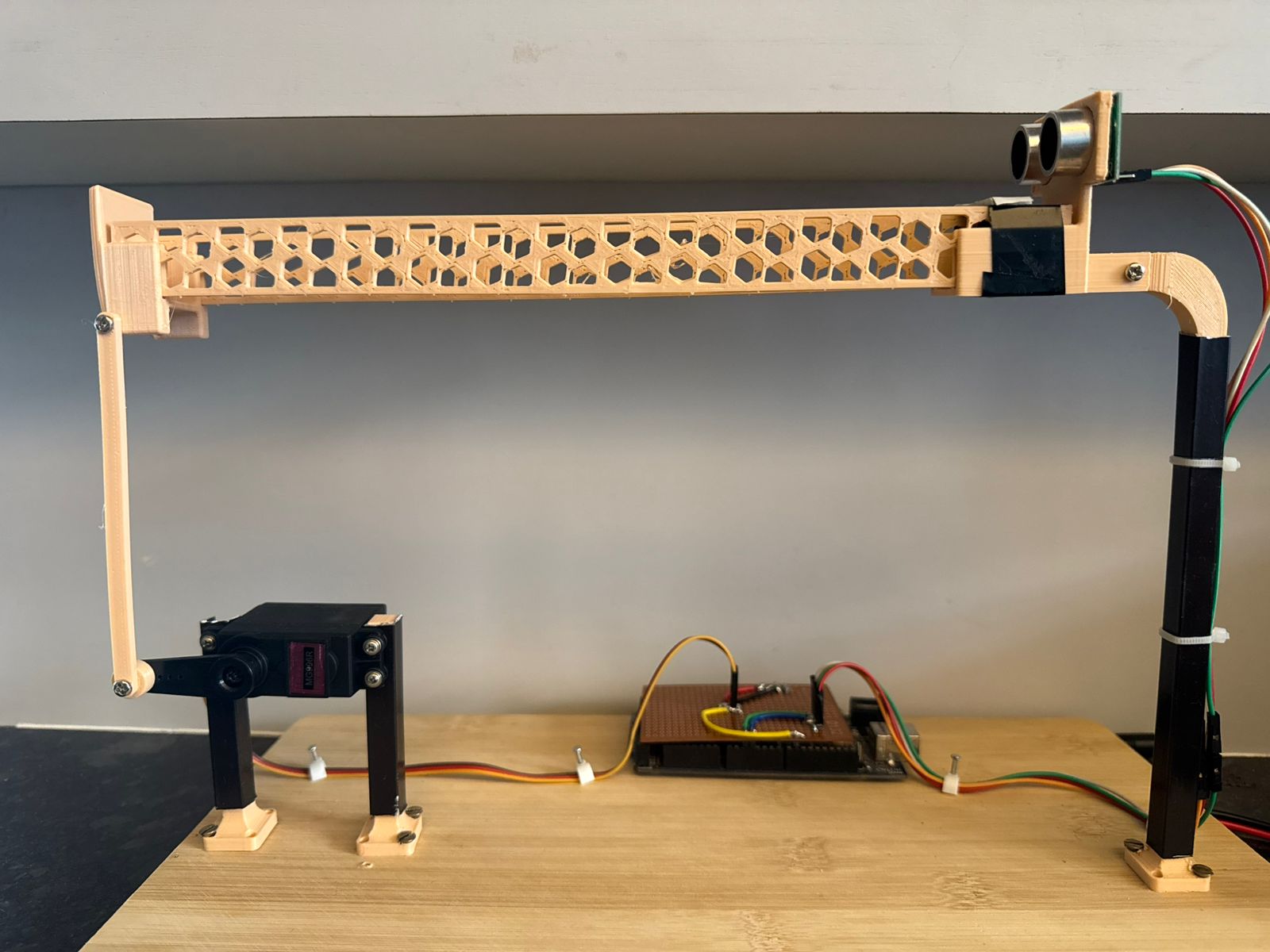
Hardware Setup
- US100 ultrasonic sensor for ball position measurement
- MG996R servo motor for beam actuation
- Arduino Mega for real-time control execution
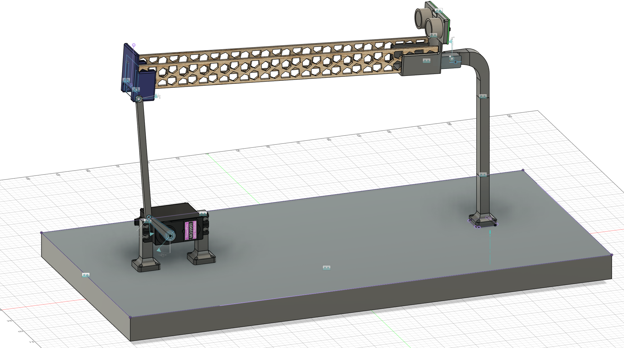
Mechanical Design
All mechanical components were designed in Fusion 360 and fabricated using 3D printing. The design prioritized modularity and ease of iteration during controller tuning.
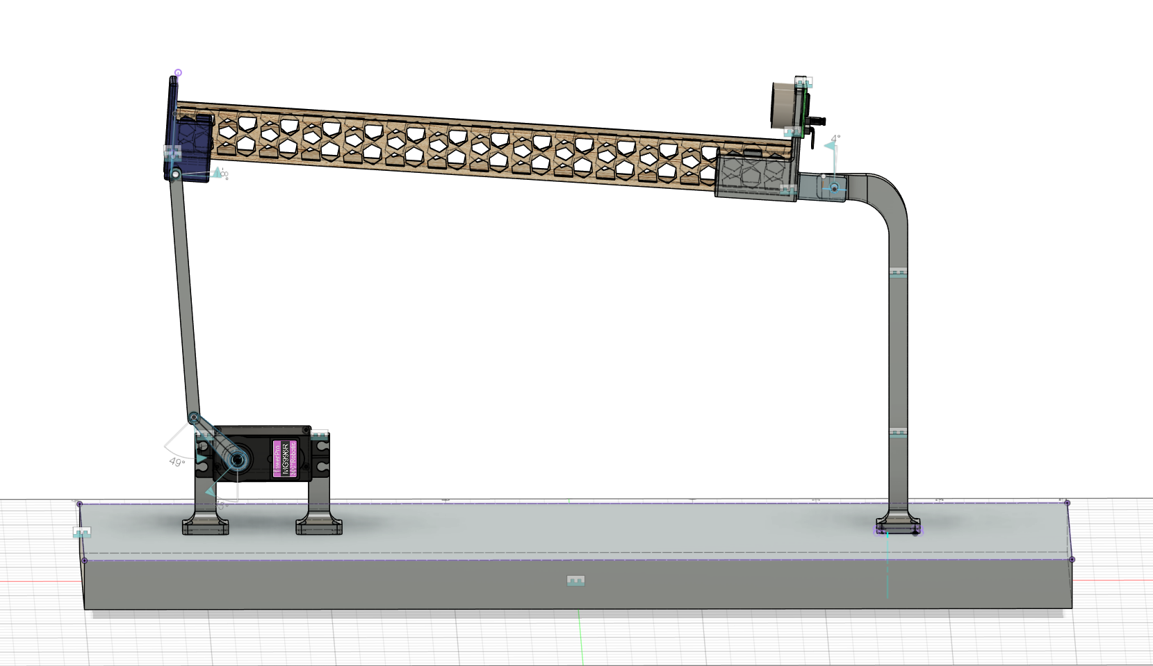
System parameters
Bridge length: 0.23m
Ball used: Standard table tennis ball
Ball radius(R) = 0.02m
Ball
Inertia(J)
4.5x10^-6 Kgm^2
Lever arm offset(d): 0.027m
Design criteria
Settling time < 5 seconds
Overshoot < 5%
Modeling and Simulation
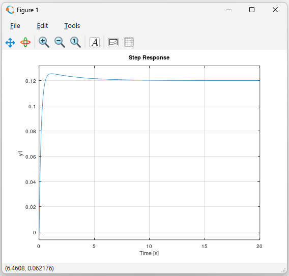
The system dynamics were derived using the Lagrangian formulation, following established ball-and-beam models. Simulations were performed using GNU Octave to analyze system response and to obtain initial controller gains. The simulated model was used to determine values of Kp and Kd that satisfied the design objectives under ideal conditions.
The following values were obtained for Kp and Kd with the following simulation results.
- Kp=8
- Kd=25
- Mp=4.53%
- Ts=3.68s
Controller Architecture
A classical PID controller was implemented in discrete time on the Arduino Mega. The control loop operated in real time, incorporating sensor feedback and servo actuation.
Experimental Implementation and Observations
Observation
Simulation-derived gains were deployed on the physical system and refined through iterative tuning. Performance deviations from simulation were observed due to:
- Extremely low ball inertia, leading to high sensitivity
- Measurement noise from the ultrasonic sensor
- Mechanical dead zone and backlash in the servo motor
Despite these non-idealities, stable control around the desired setpoint was achieved.
Results
- The effects of proportional, integral, and derivative gains on stability, overshoot, and settling time were clearly demonstrated.
- While the final response did not fully meet the original design specifications, the achieved behavior was acceptable given the system’s physical constraints.
Conclusion
This project strengthened practical understanding of feedback control and emphasized the gap between theoretical models and real-world systems. It highlighted the importance of sensor quality, actuator characteristics, and iterative tuning in embedded control applications.
Further Work
Future work will focus on improving sensing and state estimation to address measurement noise and unmodeled dynamics observed in the current system. This includes implementing observer-based approaches such as a Kalman filter or velocity observer, as well as performing system identification to obtain more accurate model parameters. Additional work includes compensating for actuator nonlinearities such as dead zones and saturation, and extending the control framework to multivariable systems with coupled dynamics, such as a Stewart platform. Improvements in sensing using camera-based position measurement would further enable higher control bandwidth and more systematic tuning and control design methodologies.
References:
Controls Tutorials by Matlab and Simulink
PID Balance+Ball | full explanation & tuning