Auto PID: DC Motor Position control
This project implements a cascaded control system for a DC motor using a low-cost quadrature encoder. The control architecture consists of a fast inner velocity loop and a slower outer position loop, with automated tuning and noise mitigation strategies to ensure stable operation. The system can operate in velocity control mode or position control mode, depending on the application.
Repositry:

Hardware
Atmega328p as the micro controller, Double BTS7960 H-Bridge Motor driver, an encoder with 12PPM and DC motor that operates at 24V
Inital problems (Noise from encoder)
The feedback came from a cheap quadrature encoder. Perfect on paper. Noisy in practice. Position was sampled every 20 ms (50 Hz), which is plenty fast, but raw encoder counts had a habit of jumping by a count or two. That’s all it takes to make a velocity estimate jitter. So the signal from this encoder was cleaned up using a 3-sample median filter to remove jitter, then further smoothed with an exponential moving average. Here are the results of the encoder reading after smoothening.
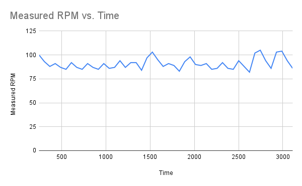
Encoder reading before noise reduction
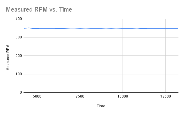
Encoder reading after noise reduction
Velocity Control and auto tuning it
The velocity loop runs every 30 ms (≈33 Hz) and sits closest to the hardware. This loop tries to maintain the set speed despite varying load and other factors, such as friction.
Since manual tuning is time-consuming and prone to error, the velocity loop is tuned using a step-input auto-tuning approach. A step input is applied, and the motor’s response is recorded. From that curve the system gain (K) comes from the steady-state response and time constant (τ) comes from how fast the motor reacts. With those two numbers, the motor is modeled as a first-order system, and Internal Model Control (IMC) rules take over. Out come Kp, Ki, and Kd are calculated. The result is a velocity loop that settles quickly and doesn’t overreact when load changes.

Velocity control loop
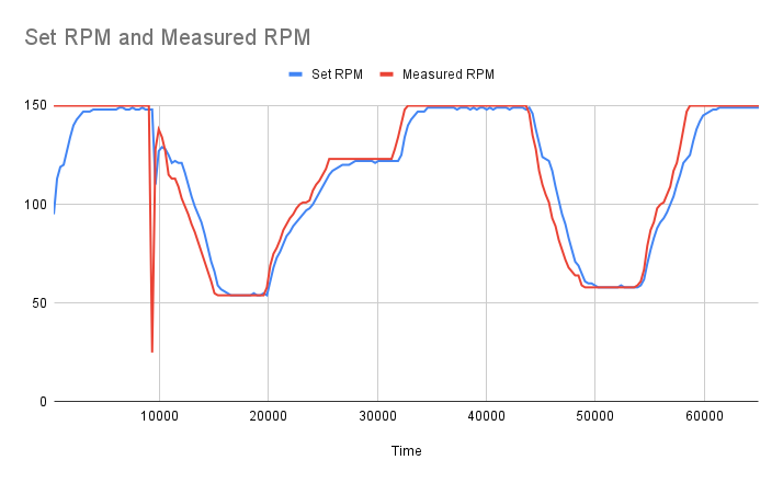
Velocity response of the motor after tuning
Cascaded Control Loops: From Velocity to Position Control
With velocity under control, position becomes much easier.
The position loop runs slower, every 60 ms (≈16.7 Hz), and outputs a velocity command rather than
driving the motor directly. In this cascaded control has the outer loop thinks in terms of where,
the inner loop worries about how fast.
Because the velocity loop already behaves like a clean first-order system, the position controller can
be tuned using the same K and τ values found earlier. No extra experiments are required.
Bandwidths stay separated, oscillations stay away, and the motor moves to the desired position.
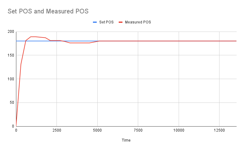
Output response of the position control loop
Having an option to set control modes allows the loop to run in velocity control or position control mode. The following block diagram shows the same.
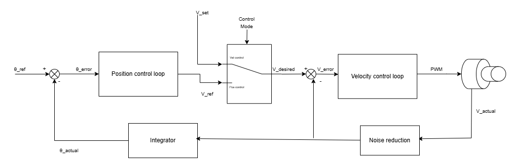
Block diagram of the control loop.
Conclusion
The key points are that accurate measurements matter as much as good controllers. Tuning the inner loop first makes later steps simpler. Model-based auto-tuning eliminates the guesswork and delivers consistent results. Most importantly, breaking the control problem into separate loops makes systems easier to tune, understand, and trust in practice.
Speed Control
Position Control: The small steady-state deviation from the set point is due to gearbox backlash.